Week 1 (04/07/17)
Week 2 (04/14/17)
- The
next step was deciding on the general structure. To brainstorm ideas, the
team did additional research on generative design and example projects.
For example, one inspiring project was a chair (Figure 1). Some goals
were: making a structure lighter, more efficient, more accessible, and
more comfortable. The group also wanted to benefit the community and
improve lives. Inspired by examples of an light, 3D-printed arm cast
(Figure 2), the team reached a final decision for a structure: an orthotic
leg cast.
- Through
the composition of the design proposal, the team identified objectives,
deliverables, technical activities, and a set up a project timeline. The team’s
goals for week three include continuing literature study and beginning the
design process.

Figure 1. Chair optimized through generative design[3]

Figure 2. Cortex cast designed by Jake Evill[4]
Week 3 (04/21/17)
- Week three focused on three goals: refining the focus of the design objective in terms of specificity, identifying medical standards, and learning to use Autodesk Fusion 360 . Specifying the type of injury the cast would serve was the first step in narrowing the objective. The severity and specific mechanism of injury determines how a patient should be treated and, if a cast is required, what type of cast would be optimal. The goal of the team’s cast is to treat fractures of the tibia and fibula (e.g. foot fractures, stress fractures, ankle fractures). After treatment the leg is immobilized with a cast to achieve correct anatomical alignment and minimize potential movement. The team will design a short-leg cast that sits below the knee that can bear the load of walking.
- Short-leg casts are commonly used to treat the movement, strength, and flexibility of the musculoskeletal system of the leg. After a literature review, the team was able to identify the medical standards of designing a short-leg cast. Three standardized aspects of the structural design need to be considered: compression of the cast, movement of the leg, and the force applied by the body. Compression is dependent on acquiring the appropriate measurements of the leg and foot that will hold bones in place while not blocking blood veins. Compression is also dependent on the leg musculoskeletal movement. The cast should have enough room for muscle contraction and flexion. During the healing recovery, injured bones and tissue will need to be able to exert minimal movements. Hence, a force will be applied by the body on the cast. Body and cast weight are the main forces that the team will consider in designing a durable cast that facilitates a fast recovery
- In terms of 3D modelling software, the team was familiar with Creo Parametric and AutoCAD, but no Autodesk Fusion 360. This software includes several distinct environment for modelling, free-form sculpting, animation, high-definition rendering, and various simulations. In order to become familiar with the unique modelling and simulation environment of Fusion 360, the team created simple figures and computed topology optimizations on the solids with user-defined loads. The original models of the figures before promoting the simulation results are shown below in Figure 2 and 3.

Figure 3. The team modelled a simple structure with a unilateral symmetry to practice using the Fusion 360 modelling environment.

Figure 4. The team also created a second figure, which will undergo topology optimization along with the previous figure.
- In the simulation environment, the group created a new study for each figure. The "shape optimization" simulation was selected, but this name is misleading. In a meeting with the project advisor, the group learned the difference between true "shape optimization" and topology optimization. Since this test removes material without modifying the internal structure of the solid, it should be called "topology optimization" instead.
- In accordance with this tutorial provided by Autodesk, the team defined loads and shape optimization criteria. Each simulation study was the solved with cloud computing with resources provided by Autodesk. For the first model, the group chose ABS plastic for the study material, and applied a load of 500N to the top face (Figure 5). The group originally set the target mass to 30% of the original figure, but the test failed. A successfully optimized figure was returned from a second test run with a target mass of 50%. The results of the simulation, animated below in Figure 6, were promoted to a final mesh (Figure 7). The colors in the animation correspond to the importance of each chunk of material in term of meeting the load bearing requirement. Point of the figure in 3D space is rated on this scale that spans from 0 to 1 with 0 being the least critical and 1 being crucial.
Figure 5. The original figure before the test with an arrow depicting the direction of the load on the upper face.
Figure 6. An animation of the topology optimization results. This shows which material can be removed to meet both the mass reduction and load bearing requirements.
Figure 7. The promoted mesh with the original figure displayed with partial opacity for visual comparison.
- The second model the team constructed for practice was tested for a 250N load (Figure 8). While the mass reduction requirement of 50% remained the same, an additional layer of complexity was added to this test. A "preserve region" constraint was added to the cylindrical hole of the model. This is indicated below in Figure 9 by the protruding green cylinder. As with the previous simulation, the results, animated below in Figure 10, were promoted to a final mesh (Figure 11).

Figure 8. The arrows indicate the direction of the 250N that was applied to the figure during the simulation.

Figure 9. The transparent green cylinder indicates the region exempt from removal during the topology optimization.
Figure 10. The animated topology optimization results. This shows which material can be removed while meeting the mass reduction and load bearing criteria and preserving the constrained region.

Figure 11. The promoted mesh from the simulation study results.
Week 4 (04/28/17)
- In
week four, the team goal was to start the modeling process while also
establishing a background analysis of the design solution. After
determining the main medical requirements of leg casts, the team wanted to
identify any constraint that need to be considered for the proposed solution.
For example, constraints that relate to the application of the cast are
the compression degree, ankle position, cast dimensions. Other constraints
are related to the recovery progress such as the conditions of the muscles
and bonds, the force direction of the body weight, and the time period of
the treatment.
- One
goal of the project was to demonstrate the patient specificity of the leg
cast. One way to achieve the required custom fit this medical device is
through capturing their leg in 3D space with reality capture. The leg cast
structure created through generative design could then be virtually fitted
to the 3D model of the patient's leg to ensure an accurate fit. The team
experimented with reality capture using a smartphone camera and Autodesk
Recap. Initially, simple objects were used to gain experience with the
process. For the first three trials, the group photographed a stapler over
a white backdrop created with printer paper. These are shown below in
order of trials. After the first trial (Figure 12), the team took another
set of images while considering the consistency of the white balance. The
focus was readjusted before taking each picture to ensure the white
balance was calibrated equally across the photo set. The results of this
trial were not significantly improved (Figure 13). To achieve an even
cleaner background, the team used Microsoft Paint to erase the shadows and
desk surface from the second set of images. The team conducted a third
trial with these edited images, and result was the closest to an actual
stapler (Figure 14).
Figure 12. First attempt with reality capture of stapler. The image set included 51 photos.
Figure 13. Second attempt. More attention was given to regulating white balance. The image set included 96 photos.
Figure 14. Third attempt. Shadows and desk surface were removed. The team modified the previous set of 96 images.
- The
team attempted to capture a clothing iron through the same process used
with the stapler. A hypothesis was made that the simple topology and
uniform color of the stapler hindered the computer's ability to accurately
place the various images in 3D space. In contrast to the stapler, the iron
had a much more complex appearance that would likely lead to fewer
ambiguities during the computation (Figure 15). However, the failed results
indicated an intrinsic flaw in the group's photography process (Figure 16).

Figure 15. One of the images take of the clothing iron for the reality capture.
Figure 13. Second attempt. More attention was given to regulating white balance. The image set included 96 photos.
Figure 14. Third attempt. Shadows and desk surface were removed. The team modified the previous set of 96 images.

Figure 15. One of the images take of the clothing iron for the reality capture.
Figure 16. The resulting model from Recap fail to resemble an iron. The image set included 120 photos.
- After consulting online tutorials and the project advisors, the team learned that the white background was the main cause of error. Using a distinctive background like newspaper provides the computer with reference points that help determine where each image should overlap in 3D space. In contrast, a perfectly white background is completely void of any reference points. The team used this new information while attempting to capture a tube of paint. Both the paint and the newspaper covered surface it rested on remained stationary while a team member walked around with a camera taking pictures. The Recap results were drastically improved over the previous attempts (Figure 17).
Figure 17. The newspaper mat helped create a recognizable model. The image set included 63 photos.
- However,
the group noticed small inaccuracies in the resulting model of the paint
tube. The smooth plastic tube appeared very rough and crinkled.
Additionally, the translucent plastic tab at the top and black cap at the
bottom were both disfigured. Such small errors in a 3D model of a leg
would possible lead to a cast that does not fit since the margin for error
is small. The team proceeded with experimentation and attempted to capture
a group member's leg. After covering the floor with newspaper, the team
member stood on one leg while they propped the other leg up on a sawhorse.
The resulting model yielded results with similar topology issues to the
previous tube of paint (Figure 18).
Figure 18. The reality capture of a leg with inaccurate surface topology. The image set included 58 photos.
- The team met with project advisors to discuss the recurring inaccuracy of the reality capture models. Another systematic flaw was identified regarding the quantity of the images taken. Additionally, the team attempted to capture the entire leg in most of the photos. In the future, the team will visually break the leg up into horizontal bands and complete more than two full passes around the leg for a more accurate result.
Week 5 (05/05/17)
- The team in week five aimed to accomplish two main
objectives that relate to the modeling process. First, knowing the
guidelines of the main structural components of a leg cast, and then use
these guidelines to begin modeling. Based on the Code of Federal
Regulations from the FDA, the medical device that is used to protect or
support a part of the body has to have these components: Cast heel, Toe
cap, Cast support, and Walking iron[5]. These components helped to
establish the general structure of our cast design.
- While the team plans to revisit the use of reality capture, the project advisors supplied a high-resolution mesh of a human leg to facilitate progress on the design of the actual cast. Through meeting with the project advisors, the group learned about Autodesk Netfabb and shape optimization. Through use of the "pull" command in Fusion 360, the group can generate a solid-walled cast. Different lattice structures and shapes can be applied to the internal structure of this cast model with Netfabb and tested for strength. In the next week, the group will work to generate this solid-walled cast model in Fusion 360.
Week 6 (05/12/17)
- This week we aimed to define our own performance requirements considering other existed solutions. The team put together a table, shown below, to compare between each solution design and build requirements upon that.
Table 1

- With the help of the project adviser, the team concluded the following performance requirements: durable for at least 6 weeks, provide impact attenuation while walking, reduce discomfort during walking and sitting, adaptable to leg geometry, breathable, to allow air circulation while worn, and resist bacterial degradation.
 |
| Figure 19: Below knee cast replacement walker [8]. |
 |
| Figure 20: Below knee cast replacement walker [9]. |
 |
| Figure 21: Patient specific ankle-foot orthoses using rapid prototyping [10]. |
- Using the pull command in Autodesk Fusion 360 and the high-fidelity human leg mesh model, the group generated a solid-walled cast (Figure 22). In the next week, the team will apply networks of different shapes to the internal structure of the cast and determine the strongest patterns in Autodesk Netfabb. Since, this feature is not available on the student version of the software, the group must utilize the computers in the office of the TAMG lab.
Week 7 (05/19/17)
- Based on existing solution the team chose to use Nylon based on its compatible characteristics. Nylon is approved by the FDA for medical applications [11] and it is convenient for daily usage for the patient. Nylon is safe and durable. It is suitable for different temperature conditions, so it can bear up to 428 F. Nylon stiffness is 90 MPa and tensile strength is 93 MPa [12]. These values will help determining the effectiveness of the cast in immobilizing the leg while walking and exerting weight force. Nylon is also waterproofed, its water absorption property in room temperature will enable the patient to wash their leg without any complications.
Week 8 (05/26/17)
- To create test and optimize the CAD model, it is important to study the human gait cycle and ground reaction forces of walking. The gait cycle is the sequence of events when the foot contacts the ground and when that same foot contacts the ground after being lifted (Figure 22). It involves forward propulsion of the center of gravity. The important thing noted from the gait cycle was the uneven distribution of weight throughout the step. The greatest impact on the leg is at initial contact, when the heel first strikes the ground, and at the terminal stance, where the foot pushes off the ground. To determine the force of this impact, the team studied ground reaction forces of walking. Luckily, the National Institute of Health published research that studied the forces in reduced-ankle plantar flexion (mimicking movement with a cast) [14]. This study found that greatest vertical force experienced was during the initial strike and push off, and peaked at 1.2 times the walker’s body weight (Figure 23). Using this information, static testing will be applied to the CAD model of the cast, applying a vertical force test of 1.2 times an average person’s body weight.

Figure 22: The eight phases of the human gait cycle [13]

Week 9 (06/02/17)
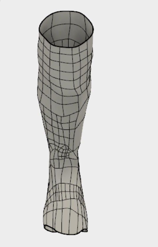
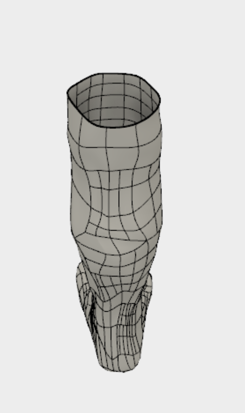
- Instead of working with results from reality capture, the team progressed to the modelling stage of the project using a high-fidelity CAD model of a human leg below the knee (Figure 24). The team decided to revisit the reality capture in the final week. This would result in higher quality meshes to prove its viability for a accessible, accurate, efficient, method of measuring legs to create a custom-fit cast. Using the free-form modelling facilitated by the sculpt environment in Autodesk Fusion 360, the team modeled a mesh surface around the existing model of the leg. The leg was broken down into the foot, the ankle, and the calf. For each section, the same basic flow of tasks was performed: create a simple geometry around the leg with multiple faces, use the pull command to form the shape around the leg more accurately, fine tune the surface mesh by splitting the faces into smaller faces and manipulating the faces individually with scaling, rotating, and translating. For the foot and the calf, hollow cylinders were used. After much trial and error, a quadball (similar to a sphere) was used around the ankle instead of a cylinder. In order to fuse these models in a single surface mesh, overlapping faces were deleted and the merge edge command was used. For the ankle, faces at the top and front of the quadball were removed to open up the solid and attach it to the hollow cylinders. After several hours of localized, fine-tuning manipulations, the team achieved a surface mesh that closely resembled the form of a human leg (Figure 25).

Figure 24. High fidelity leg model used as a foundation for the cast mesh.


- The team struggled to find the ideal material and shape for the sole of the leg cast. While the nylon material of the cast is used to bear the load of human locomotion, it cannot withstand the horizontal friction force of walking. An additional component would have to accommodate the rubbing agains the ground on impact to prevent the erosion of the nylon cast. Current solutions exist for this problem, such as wearing a special shoe over the cast (figure 26), or inserting/attaching a rubber platform to the bottom of the cast (figure 27). In future designs of the cast the material of the bottom of the cast can be altered to be replaceable or able to withstand greater amounts of horizontal friction forces.Figure 26:Ossur Multi Blue Canvas Cast Shoe [15].Figure 27: Walking Cast Rubber Orthopedic Heel [16].

References:
[1] S. W. Kielarova, P. Pradujphongphet and I. L. J. Bohez, "An approach of generative design system: Jewelry design application," 2013 IEEE International Conference on Industrial Engineering and Engineering Management, Bangkok, 2013, pp. 1329-1333. doi: 10.1109/IEEM.2013.6962626
[2] Autodesk. What is Generative Design. [Online]. Available: https://www.autodesk.com/solutions/generative-design[3] N. Baklitskaya. (2016). Generative Design: Optimization and Creativity at their Best [Online]. Available at: https://www.accenture.com/us-en/blogs/blog-generative-design-optimization-creativity-best
[4] J. Evill. (2013). Cortex. [Online]. Available at: http://www.evilldesign.com/cortex
[5] S. W. Eathorne and T. M. Sheperd, Cast Immobilization and Upper Extremity Splinting in Pfenninger and Fowler's Procedures for Primary Care, n.d, ch.187, 1255-126 Link: https://www.clinicalkey.com/#!/content/book/3-s2.0-B9780323052672001874?scrollTo=%23hl0000260
[6] A. S. Boyed, H. J. Bemjamin, and C. Asplund, “Splints and Casts: Indications and Methods,” American Family Physician, vol. 80, no. 5, Sep. 2009.
[7] “CFR - Code of Federal Regulations Title 21,” accessdata.fda.gov. [Online]. Available: https://www.accessdata.fda.gov/scripts/cdrh/cfdocs/cfcfr/cfrsearch.cfm?cfrpart=888&showfr=1&subpartnode=21%3A8.0.1.1.31.5. [Accessed: 1-May-2017].
[8] H. D. Darby, “Below knee cast replacement walker ,” 12-Sep-2002.
[9] J. Evill. (2013). Cortex. [Online]. Available at: http://www.evilldesign.com/cortex
[10] C. Mavroidis, R. G. Ranky, M. L. Sivak, B. L. Patritti, J. Dipisa, A. Caddle, K. Gilhooly, L. Govoni, S. Sivak, M. Lancia, R. Drillio, and P. Bonato, “Patient specific ankle-foot orthoses using rapid prototyping,” Journal of NeuroEngineering and Rehabilitation, vol. 8, no. 1, 2011.
[11] Center for Devices and Radiological Health, “3D Printing of Medical Devices - Medical Applications of 3D Printing,” U S Food and Drug Administration Home Page. [Online]. Available: https://www.fda.gov/MedicalDevices/ProductsandMedicalProcedures/3DPrintingofMedicalDevices/ucm500539.htm.
[12] Ertalon, “Technical Data Sheet for Nylon 66 Rod, Sheet & Tube.” Jan-2011. [Online]. https://www.theplasticshop.co.uk/plastic_technical_data_sheets/nylon_66_technical_data_sheet.pdf
[13] Streifeneder Ortho Production, The eight phases of human gait cycle. 2017. [Online]. Available: https://www.streifeneder.com/downloads/o.p./400w43_e_poster_gangphasen_druck.pdf
[14] T.-wei P. Huang, K. A. Shorter, P. G. Adamczyk, and A. D. Kuo, “Mechanical and energetic consequences of reduced ankle plantar-flexion in human walking,” The Journal of Experimental Biology, Nov-2015. [Online]. Available: https://www.ncbi.nlm.nih.gov/pmc/articles/PMC4664043/. [Accessed: 02-Jun-2017].
[14] T.-wei P. Huang, K. A. Shorter, P. G. Adamczyk, and A. D. Kuo, “Mechanical and energetic consequences of reduced ankle plantar-flexion in human walking,” The Journal of Experimental Biology, Nov-2015. [Online]. Available: https://www.ncbi.nlm.nih.gov/pmc/articles/PMC4664043/. [Accessed: 02-Jun-2017].
[15] “OrthoTape | Casting and Bracing Superstore,” OrthoTape.com. [Online]. Available: https://www.orthotape.com/mulit_blue_Canvas_cast_shoe.asp. [Accessed: 02-Jun-2017].
[16] “OrthoTape | Casting and Bracing Superstore,” OrthoTape.com. [Online]. Available: https://www.orthotape.com/cushion_tread_walking_cast_heel.asp. [Accessed: 02-Jun-2017].
